
Knowledge page · Emergency power
Emergency power systems: the whole chain from grid to load
An emergency power system is not one machine but a chain of units that must take over in the right order and at the right time. Here is the chain, the requirements for how fast and how long, and how redundancy is built.
The chain
Which links an emergency power system consists of, and what supplies the load from the first millisecond to hours after the outage.
In short
What is an emergency power system?
An emergency power system is the units that together keep the supply going when the grid fails. Each unit covers its part of the time – none of them can do it alone.
Safety or operations? A safety supply protects people, e.g. emergency lighting. A standby supply keeps operations running. That decides which rules apply and who sets the requirements.
The links
Seven links – one system
Choose a link and see what it does in the chain. The order follows the power from the grid to the load.
01 · The normal supply
Mains
The supply from the grid. It fails not only as a complete outage – voltage dips and disturbances can also stop sensitive equipment.
02 · The long autonomy
Generator plant
Takes over when the grid is gone for more than a few seconds. A diesel generator plant can typically take full load within approx. 10 seconds and runs as long as there is fuel.
Generator plants03 · Mains or generator
Transfer switch
The automatic transfer switch (ATS) moves the supply from mains to generator and back again. It switches mechanically, so the load behind it sees an interruption.
04 · No interruption
UPS
Keeps the critical load supplied without interruption while the generator starts, and cleans the power of disturbances from the grid and the generator.
Borri UPS systems05 · Batteries or flywheel
Energy storage
Batteries or a flywheel in a rotary UPS deliver the energy during the transition. The storage only has to last until the generator has taken over – but it has to work every time.
Rotary UPS / DRUPS06 · Two sources, one load
STS
A static transfer switch gives equipment with one power supply access to two independent UPS supplies and transfers in a few milliseconds.
Borri STS 30007 · Switchboards and cables
Distribution
Switchboards, cables and protection carry the power to the load. A shared switchboard or breaker hits everything behind it if it fails – no matter how much redundancy stands in front of it.
An outage in time
Who carries the load when?
The critical load behind the UPS notices nothing: the energy storage takes over immediately, and the generator takes over after approx. 10 seconds. The other load behind the transfer switch is without power until the generator is ready.
The requirements
How fast the supply must be back and how long it must last – according to the standards and the load.
Changeover time
Six classes – from no break to more than 15 seconds
IEC 60364-5-56 classifies automatic safety supplies by how quickly they are available after an outage. The class is chosen from what the load can tolerate.
Class A requires a UPS or rotary UPS, because nothing else delivers without a break. A generator plant alone typically lands in class E.
Two kinds of supply
Safety supply or standby supply
The same generator can supply both, but the requirements come from different places. The safety supply is regulated; the standby supply is a business decision.
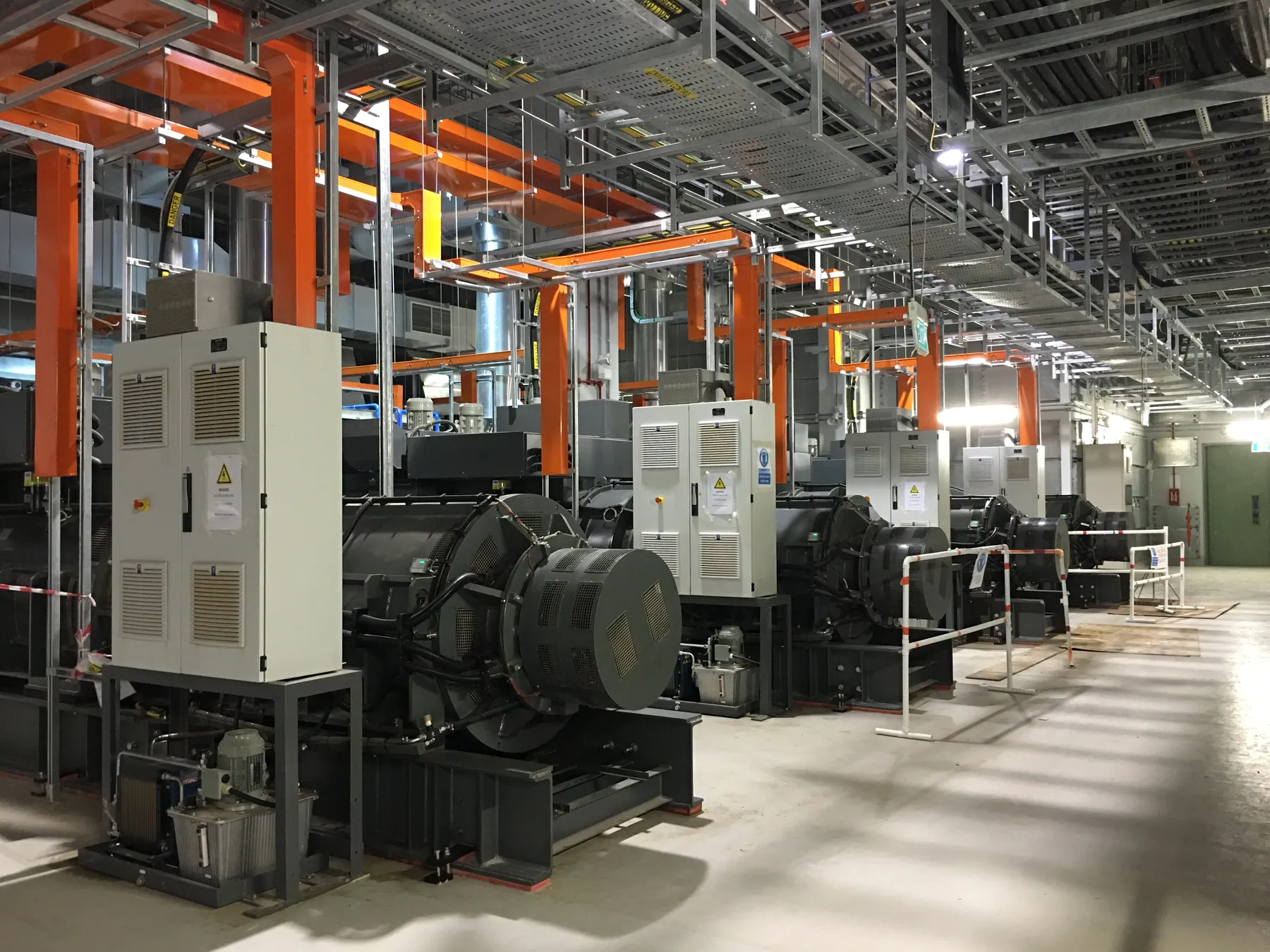
| Safety supply | Standby supply | |
|---|---|---|
| Purpose | Protect or warn people | Keep operations running |
| Examples | Emergency lighting, fire safety systems, smoke extraction | IT, cooling, production, communication |
| Standard | IEC 60364-5-56 | Outside IEC 60364-5-56 |
| Requirements set by | Standards and authorities | The contingency plan and the owner |
Requirements by sector
Hospitals, emergency lighting and data centres
Some sectors have fixed requirements for time and duration. They are a minimum – the contingency plan may require more.
| Sector | Standard | Requirement |
|---|---|---|
| Hospitals | IEC 60364-7-710 | ≤ 0.5 s for e.g. operating theatre lights for at least 3 hours · ≤ 15 s for other essential equipment for at least 24 hours |
| Emergency lighting | EN 1838 · EN 50171 | At least 1 hour on escape routes · central systems recharge to 80 % within 12 hours |
| Data centres | EN 50600 | Availability class 1–4: from one supply path without redundancy to several fault-tolerant paths |
Redundancy
How the chain is made robust – and where it typically breaks anyway.
Redundancy
N, N+1 or 2N?
EN 50600 links power supply redundancy to the data centre availability class. The principle applies to all critical installations: the fewer shared points, the fewer faults reach the load.
N
Class 1Exactly the capacity the load requires. One fault or one service visit stops the supply.N+1
Class 2One extra unit. One UPS or one module can fail or be serviced – but there is still one supply path.2N
Class 3–4Two complete, independent supply paths. A whole path can fail or be maintained without affecting the load.
Classes to EN 50600-2-2. Principle – the actual design depends on the installation.
Single points of failure
Where the chain most often breaks
Redundancy only moves the risk if it is carried all the way to the load. It is the shared points that decide uptime.
- 01Shared switchboard or breakerTwo UPS systems do not help if they supply through the same switchboard.
- 02Bypass and transfer switchManual and automatic transfer switches are often the only link that is not duplicated.
- 03Starting batteries and fuelThe generator only starts if starting batteries, preheating and fuel are in order.
- 04Age of the energy storageBatteries lose capacity with age. The transition is short – but it has to hold every time.
- 05Control powerControls, relays and monitoring must themselves have a secure supply.
- 06Load outside the planNew equipment is connected over time. Without a load schedule, the system can be too small when it matters.
Operation
How the system is proven and kept ready – and where the requirements come from.
Testing
Four levels of testing
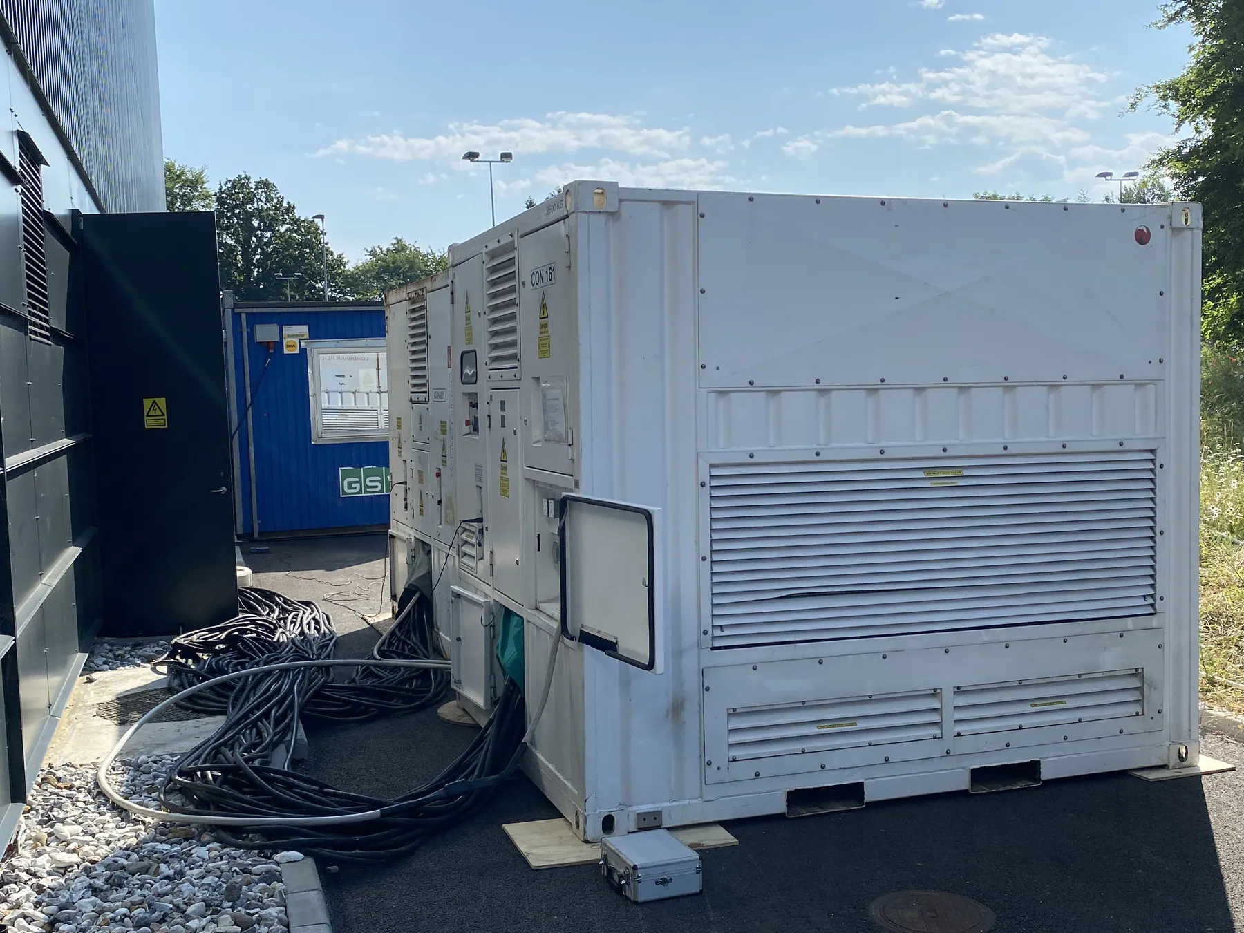
Each unit can pass its own test while the chain fails in the interaction. That is why the simulated mains failure is the test that shows whether the system works when it matters.
| Test | What | Shows |
|---|---|---|
| Component test | Each unit on its own: UPS, batteries, generator, transfer switch | That the unit works |
| Load test | UPS and generator under full load with load bank | That the power is there |
| Simulated mains failure | The whole chain takes over under real load – and transfers back | That the chain works together |
| Integrated systems test (IST) | Power, cooling and controls tested together at commissioning | That the building works |
Our partner Bluecircle carries out commissioning and integrated systems testing: Commissioning.
Contingency plan
The plan decides the system – not the other way round
Which functions must keep running, for how long, and what interruption can they tolerate? The answers give the changeover class, autonomy and redundancy. Without them, the system is sized by guesswork.
- 1FunctionsWhat must run?
- 2InterruptionWhat can be tolerated?
- 3DurationFor how long?
- 4SystemClass, autonomy, redundancy
FAQ
Questions and answers about emergency power systems
Can’t find the answer? Give us a call.
+45 50 53 13 17What is an emergency power system?
An emergency power system is the units that together keep the supply going when the grid fails: typically UPS with batteries or flywheel, generator plant, transfer switch and the distribution that carries the power to the load. The system is only as good as the weakest link in the chain.
What is the difference between an emergency power system and a UPS?
A UPS is one link in an emergency power system. It keeps the load supplied without interruption for minutes. The long autonomy comes from a generator plant, and the transfer switch and distribution tie the units together.
How fast must emergency power be available?
It depends on the load. IEC 60364-5-56 divides safety supplies into classes from A (no-break) via C (at most 0.5 s) and E (at most 15 s) to F (more than 15 s). In practice IT equipment needs a no-break supply, while much other load can wait for the generator.
What is the difference between a safety supply and a standby supply?
A safety supply protects or warns people, e.g. emergency lighting and fire safety systems, and is covered by IEC 60364-5-56. A standby supply keeps operations running for reasons other than safety, e.g. IT, cooling and production – here the contingency plan sets the requirements.
Which requirements apply to hospitals?
IEC 60364-7-710 requires supply within 0.5 s for e.g. operating theatre lights for at least 3 hours, and within 15 s for other essential equipment for at least 24 hours.
What do N, N+1 and 2N mean?
N is exactly the capacity the load requires. N+1 has one extra unit, so one can fail or be serviced. 2N is two complete, independent supply paths. EN 50600 links redundancy to availability classes 1 to 4 for data centres.
How is an emergency power system tested?
The most realistic test is a simulated mains failure in which the whole chain must take over under real load: the UPS bridges, the generator starts, the transfer switch transfers and the mains returns. How often this happens should be set in the contingency plan.
Do you have a project or a system that needs service?
Send us the load, required autonomy and voltage level – or describe the task. We will come back with a solution sized for your operation.