Knowledge page · Dynamic UPS
Rotary UPS and DRUPS
How a rotary UPS and a diesel rotary UPS (DRUPS) work, what to examine before you choose, and all current models from HITEC, Piller and Active Power.
Understand the technology
What a rotary UPS is, how a DRUPS works and how much time the rotating energy gives.
In short
What is a rotary UPS and a DRUPS?
A rotary UPS stores energy in a rotating mass – typically a flywheel – instead of in batteries. When the grid fails, the rotating energy keeps the load supplied without interruption.
A DRUPS is a rotary UPS with a built-in diesel engine. The engine starts while the flywheel carries the load and then takes over the supply as long as there is fuel.
The technology is used mainly in data centres, hospitals, airports and industry, where UPS and standby power are combined in one machine. Designs vary between manufacturers, so clutch, energy store, controls and cooling must be assessed for the specific system.
Types
Three types of rotary UPS
The term rotary UPS covers three basic types. The difference lies in where the energy comes from when the grid is lost, and what takes over if the outage lasts.
Flywheel UPS
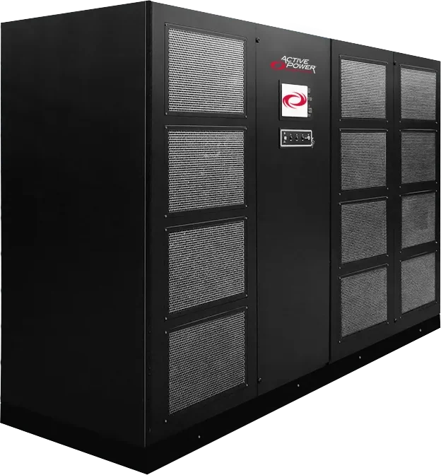
Active Power CleanSource HD
A flywheel supplies power for up to approx. 2 minutes while a separate generator starts.
DRUPS
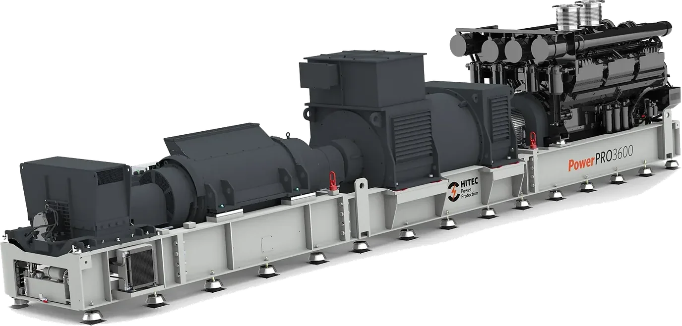
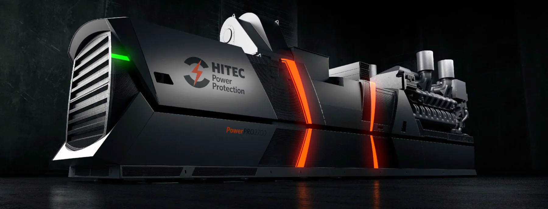
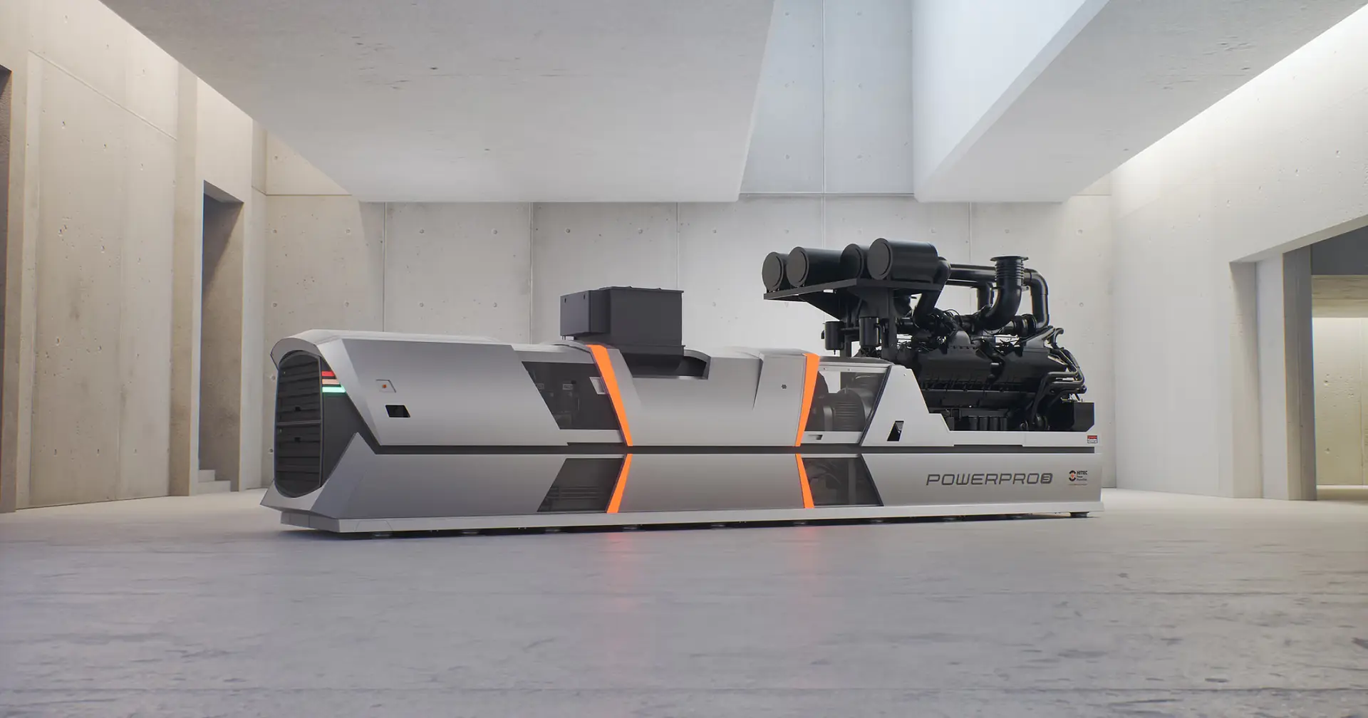
HITEC PowerPRO3600
Flywheel, diesel engine and generator on one shaft. The flywheel bridges until the engine runs.
Separate energy store
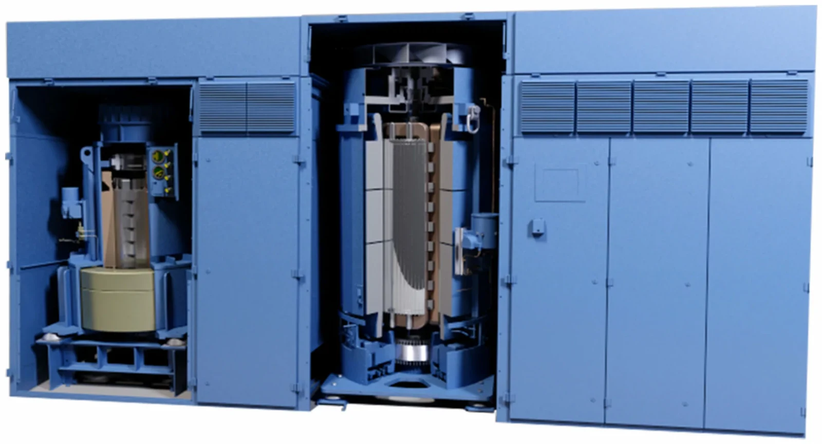
Piller UNIBLOCK UBTD+
Flywheel or battery connected electrically to the machine, with built-in or external engine.
Operation
How a DRUPS works
In normal operation the grid drives the machine as a motor and keeps the energy store spinning. Together with the choke, the machine stabilises the supply and damps voltage dips and harmonic currents.
When the voltage is lost or leaves its limits, the stored energy keeps the generator running while the diesel engine starts and engages. With mtu, the kinetic energy also helps the engine up to speed quickly, so the load does not notice the transfer.
- 1Normal operationSupplies the load: Grid
The grid drives the synchronous machine as a motor. The energy store is kept up to speed, and the choke filters the supply.
- 2Mains failureSupplies the load: Kinetic energy
The system detects the fault, disconnects the grid and supplies power from the rotating mass. The load sees no interruption.
- 3Engine startSupplies the load: Kinetic energy
The diesel engine starts, accelerates and engages via the clutch while the energy store still carries the load.
- 4Island modeSupplies the load: Diesel
The engine delivers the mechanical power. The system runs as long as there is fuel and recharges the energy store at the same time.
- 5Mains returnSupplies the load: Grid
When the grid is stable, the system synchronises and transfers the load back. The engine cools down and stops.
Kinetic energy
How much ride-through do you get?
The rotating mass stores kinetic energy. The amount depends on the moment of inertia J and the angular velocity ω:
E = ½ · J · ω²
Because speed is squared, small changes in speed matter a lot. HITEC, for example, states 25% more energy in the latest module for the PowerPRO3. But not all the energy can be used: the generator must keep voltage and frequency within the load’s limits. If speed falls from 100% to 90%, only 19% of the energy is released.
Ride-through depends on
- 01The load’s power and power factorThe larger the load, the faster the speed drops.
- 02Size and speed range of the energy storeDetermines the energy that can actually be used.
- 03Load steps during engine startDraw extra energy during the transfer.
- 04Engine start and engagement timeThe time the energy store carries the load alone.
- 05Controls and settingsE.g. delayed engine start for short outages.
Mains disturbances
Fewer diesel starts with longer ride-through
Most mains failures last less than one second. If the diesel engine starts on every disturbance, it runs many short, unnecessary starts – with wear, fuel use and emissions as a result.
A DRUPS with a large energy store can delay the engine start and let the store handle the short failures. Piller states that the diesel start delay on the UNIBLOCK UBTD+ can be set from seconds to minutes.
So don’t just ask how fast the engine starts – ask how often it has to.
Energy storage
Flywheel or battery?
The ride-through energy can come from a flywheel or – on some designs, such as Piller UNIBLOCK UBTD+ – from batteries. The choice shifts space, efficiency and the number of diesel starts.
| Flywheel | Battery | |
|---|---|---|
| Space | Compact; no air-conditioned battery room | Requires a battery room with cooling |
| Electrical efficiency | Lower than battery – the flywheel has running losses | Higher than an equivalent kinetic store (Piller) |
| Autonomy | Seconds to a few minutes | Can be sized longer – even fewer diesel starts |
| Recharge | Can absorb energy as fast as it releases it (POWERBRIDGE) | Slower; limited by the charger |
| Life and environment | No battery replacement or disposal | Replaced during the plant life; must be disposed of |
Assess the design
The technical questions that separate a good DRUPS project from a datasheet.
Design
Mechanically and electrically coupled designs
In some systems the diesel engine, clutch, energy store and generator sit on one shaft. In others the energy store is a separate unit connected electrically to the machine. The difference decides how energy is transferred, how the engine engages and how the system responds to load steps and faults.
HITEC PowerPRO360001
Mechanically coupled
Everything sits on one shaft. Examples: HITEC PowerPRO, mtu Kinetic PowerPack.
- DieselEngine
- ClutchFreewheel or electromagnetic
- Kinetic energy moduleFlywheel on the shaft
- Synchronous machineMotor/generator
- LoadVia choke
Piller UNIBLOCK UBTD+02
Electrically coupled
The energy store is a separate unit. Example: Piller UNIBLOCK UBTD+.
- DieselEngine
- ClutchFreewheel
- Motor-generatorThe UNIBLOCK machine
- LoadVia choke
Mechanical shaftElectrical connection
The two basic ways to build a DRUPS.What the project must clarify
- 1Which machine architecture is used?
- 2How is energy transferred from store to generator?
- 3What happens if the engine fails to start?
- 4Can the system provide UPS function during engine service?
- 5Which operating modes and bypass options exist?
- 6How are mains return and parallel operation handled?
Load
Load steps, harmonic currents and fault current
The load in a data centre or factory changes quickly when UPS modules, chillers, pumps and motors start and stop. Three issues need particular attention.
- 01
Load steps
A large, sudden load step makes voltage and frequency dip before the engine and controls have stabilised.
Ask for: Largest single load, motor starts, transformer energisation and simultaneous restart.
- 02
Harmonic currents
Non-linear loads stress generator, cables and components. The choke and rotating machine can damp them.
Ask for: Measured or calculated performance for your load.
- 03
Fault current
The generator’s fault current differs from the grid’s. Protection and selectivity must work in both grid and island mode.
Ask for: A protection study for both operating modes.
Power quality
A filter that works both ways
The load is supplied through a choke and a synchronous machine. This damps sags, spikes and harmonics from the mains – and keeps the load’s own harmonics away from the mains. Piller points out that the UBTD+ has no power capacitors in the supply path.
Figures: Piller for UNIBLOCK UBTD+. Require the values documented for the specific machine.
Selectivity
Fault current that makes the breaker work
When a feeder short-circuits, the nearest breaker must trip while the rest of the plant keeps running. That requires enough fault current. A synchronous machine has low sub-transient reactance and can deliver fault current similar to a normal supply transformer. A static UPS inverter limits the current to protect itself and typically transfers to bypass on large faults.
Selectivity must still be documented in a selectivity study for the specific plant.
Case · Piller
Toulouse-Blagnac Airport
Runway lighting is supplied through several step-up and step-down transformers that the UPS alone must energise. The system must therefore deliver high inrush currents and a high short-circuit current so selectivity holds in all operating modes. The airport chose Piller’s electrically coupled UBTD+ over mechanically coupled alternatives for a larger energy reserve, better efficiency and lower maintenance cost, according to Piller.
Transfers
Mains failure and re-connection
The system must detect the fault, isolate the installation from the grid and keep the load supplied while the engine starts. Mains return is equally important: the system must check grid quality, synchronise and manage the load transfer.
- 1Grid operationThe grid is within limits and supplies the load.
- 2DisconnectionThe fault is detected and the grid disconnected.
- 3Island modeThe diesel engine carries the load.
- 4Grid checkVoltage and frequency must be stable for the set time.
- 5SynchronisationPhase, frequency and voltage are matched and the load transferred back.
What the design must describe
- 1Which deviations trigger the transfer to standby power?
- 2How is back-feeding into the disconnected grid prevented?
- 3Which deviations can the load see during the transfer?
- 4How do synchronisation and re-connection work?
- 5What happens with repeated or unstable outages?
Redundancy
Where are the common failure points?
Several DRUPS units give capacity and redundancy – but only if a fault in a shared component cannot hit them all. Otherwise the component is a single point of failure.
N+1 only gives the intended reserve if the remaining units can carry the entire load without exceeding their limits. Test it in both functional testing and scenario analysis.
One fault here can take out all four units – the reserve does not help:
Configurations
Four ways to connect several machines
One DRUPS is rarely enough. The configuration decides how redundancy, fault current and maintenance fit together – and how large the plant can become.
Parallel redundant
The units share a common bus. At low voltage, simple paralleling is limited to approx. 5 MW (Piller).
Isolated redundant
Each unit has its own load. A reserve unit normally runs without load and takes over automatically if a unit fails – without going to bypass.
Isolated parallel (IP)
The units are connected to a common IP bus through chokes. Gives large N+1 systems without high fault currents and can be maintained in operation. Piller: up to 40 MW.
Dual output
The same machine supplies both no-break to the critical load and short-break to e.g. cooling and lighting – like a built-in standby generator.
Building
Ventilation, cooling, exhaust and fuel
A DRUPS gives off heat all the time because machines and energy store rotate. In standby operation, engine heat, combustion air and exhaust are added. Ventilation is therefore part of security of supply: if the room gets too hot, performance can drop precisely during a long outage.
HVO HITEC PowerPRO3 and mtu Kinetic PowerPack are approved for HVO to EN 15940 with no loss of performance, according to the manufacturers.
- 1Cooling air inNormal and diesel operation
- 2Combustion airDiesel operation only
- 3Warm air outLosses from machines and engine
- 4ExhaustExhaust pipe and silencer
- 5FuelDay tank, main tank, filtration, pumps, alarms and refuelling
| Need | Normal operation | Diesel operation |
|---|---|---|
| Cooling | Losses from machines and energy store | Far more heat from engine and generator |
| Air | Cooling air | Cooling and combustion air |
| Exhaust | None – the engine is at rest | Correctly sized exhaust routing |
| Noise | Low | High – silencing and vibration isolation |
Size and compare
From critical load to installed power – and how DRUPS compares with a static UPS and generator.
Sizing
Example: 2.4 MW critical load
An illustrative example, not a specific project: an installation has a 2.4 MW critical load. With 25% room for growth the system must deliver 3.0 MW – also when one unit is out.
| Step | Topic | Question |
|---|---|---|
| 1 | Continuous load | What power must be supplied at all times? |
| 2 | Load steps | Which motors, chillers or transformers switch in suddenly? |
| 3 | Growth | How much capacity is expected to be added? |
| 4 | Redundancy | Must one unit be removable without interrupting the load? |
| 5 | Run time | How long must the system run on fuel? |
| 6 | Failure scenarios | Loss of a unit, switchboard section or shared auxiliary system? |
Comparison
DRUPS or static UPS with diesel generator?
The alternative to DRUPS is typically a static UPS with batteries and a separate diesel generator. Read more about static systems in All about UPS systems at Bluecircle.
Manufacturers highlight high power, integrated standby power and fewer batteries. What matters is whether the documented properties fit your load, operating strategy and maintenance requirements.
Total cost of ownership
The losses cost more than the machine
Piller writes that in most TCO calculations the electricity cost of losses is the largest item – larger than purchase and maintenance. Losses must also be cooled away, which adds further consumption.
Loss = P × (1/η − 1)
Example: 2 MW load around the clock. The difference between 97% and 94% efficiency is approx. 576 MWh a year – before cooling. Multiply by your electricity price.
Choose and operate
Where DRUPS makes sense, all current models – and how to keep the system ready.
Applications
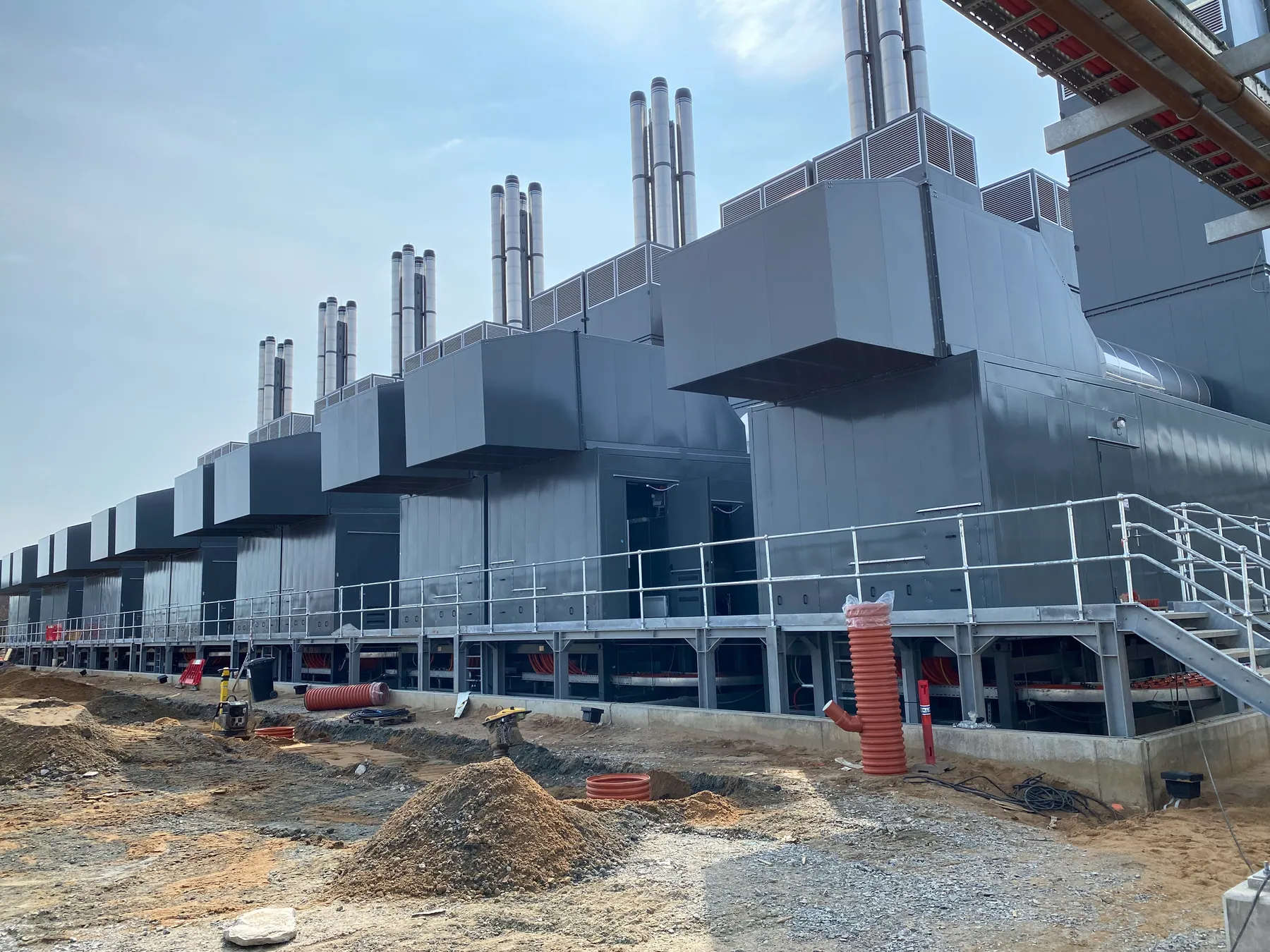
When is a DRUPS relevant?
When the installation has high power, critical loads and a need for both seamless transfer and long standby power.
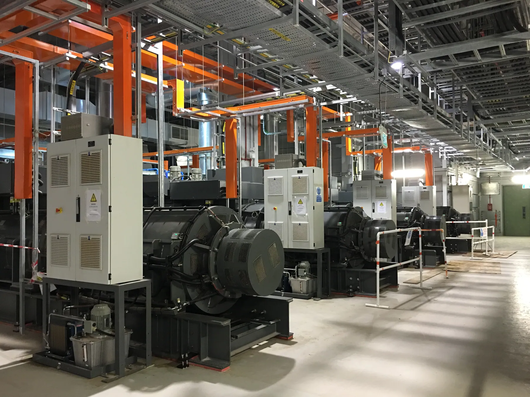

Go ahead with a DRUPS analysis if
- The load is large or has significant motor starts.
- An integrated rotary solution fits the building’s supply.
- Battery-free energy storage is a requirement or advantage.
- Space, cooling and maintenance can be designed realistically.
- Redundancy and fault-handling requirements can be met.
Products
All current models
Four selected systems followed by the full range from HITEC, Piller and Active Power. Filter by manufacturer and type.
Latest generation · HITEC
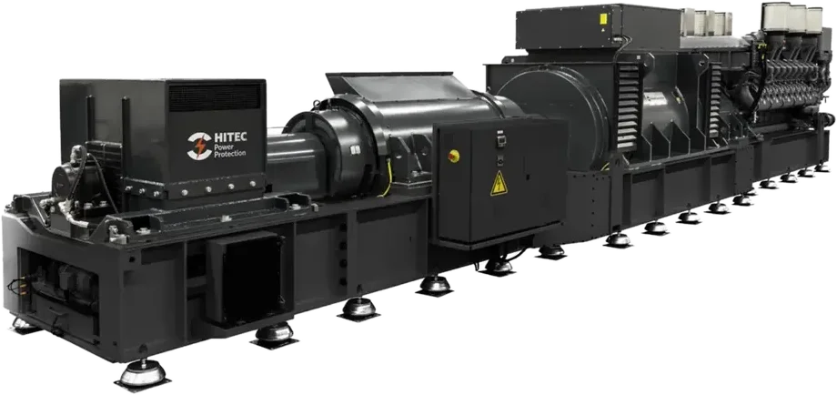
HITEC PowerPRO3
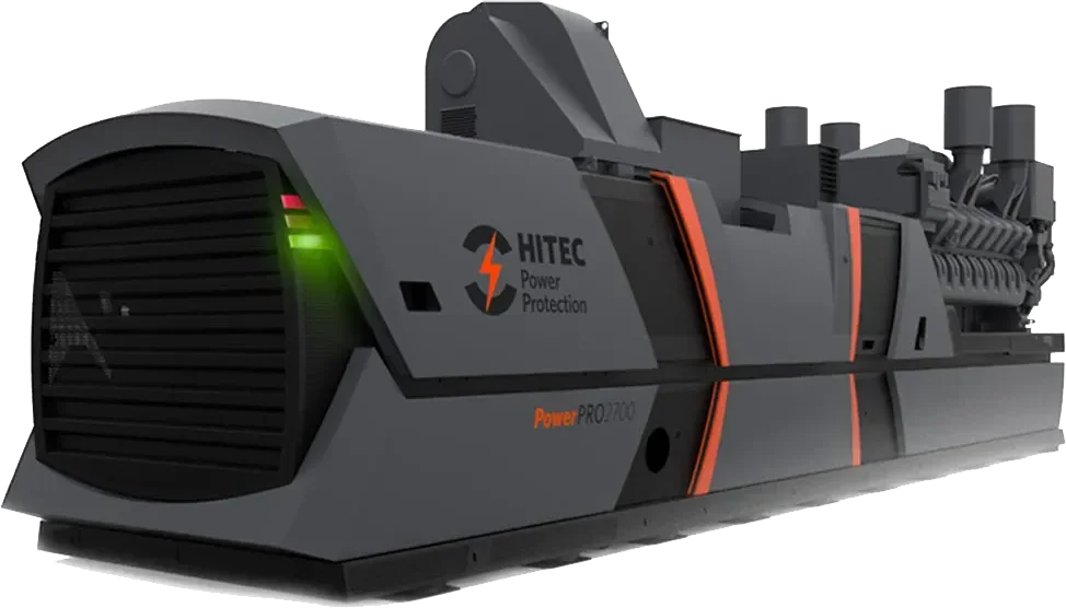
New kinetic energy module with 25% more energy, Cummins G-Drive engine and approved for HVO. Succeeds the PowerPRO2700 in the same footprint.
15 products
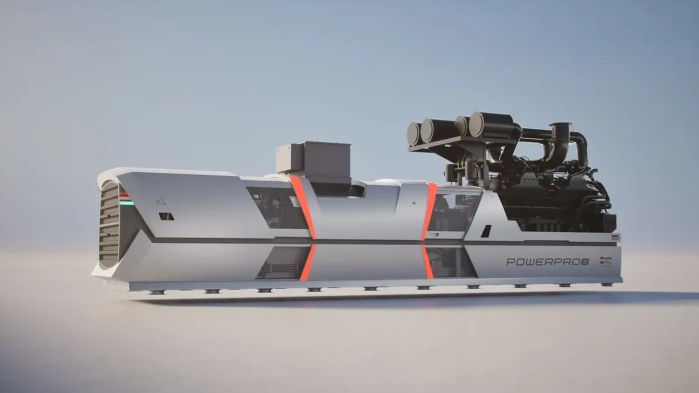
HITEC PowerPRO3
DRUPS · Up to 2500 kVA (50 Hz) / 3000 kVA (60 Hz)
- Power 50 Hz: 2500 kVA / 2000 kW (50 Hz)
- Power 60 Hz: 3000 kVA / 2400 kW (60 Hz)
- Efficiency: Up to 97 %
HITEC PowerPRO3600
DRUPS · 2500–3000 kVA (50 Hz) / 2500–3600 kVA (60 Hz)
- Power 50 Hz: 2500 / 2850 / 3000 kVA @ 400 V 50 Hz
- Power 60 Hz: 2500 / 2850 / 3600 kVA @ 480 V 60 Hz
- Efficiency: Up to 97 %
Piller UNIBLOCK™ UBTD+
DRUPS · 500–2700 kW per machine
- Power: 500–2700 kW
- Parallel: Up to 40 MW
- Efficiency: Up to 97 % with energy store connected
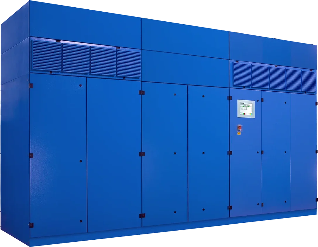
Piller UNIBLOCK™ UBT+
Rotary UPS · 500–2700 kW per machine
- Power: 500–2700 kW
- Parallel: Up to 40 MW
- Efficiency: Up to 97 %
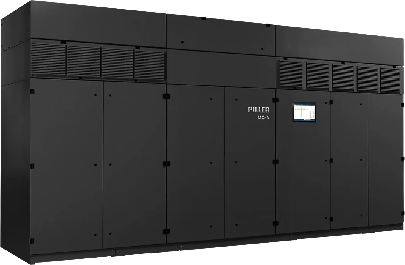
Piller UNIBLOCK™ UB-V Series
Rotary UPS (electrically coupled) · 1.0–3.24 MW (1.1–3.6 MVA) per unit
- Power: 1.0–3.24 MW / 1.1–3.6 MVA
- Parallel: Up to 100 MW / 115 MVA
- Efficiency: Up to 98 % at 100 % load, 97 % at 50 % (IEC 62040-3)
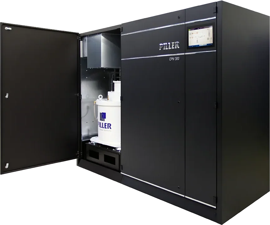
Piller CPM 300 / 360
Flywheel UPS · 300/360 kW modules, up to 2400/2880 kW
- Power: 300 / 360 kW per module
- Parallel: Up to 8 units (2400/2880 kW)
- Efficiency: Above 96 % at 25 % load, up to 98.5 % (IEC 62040-3)
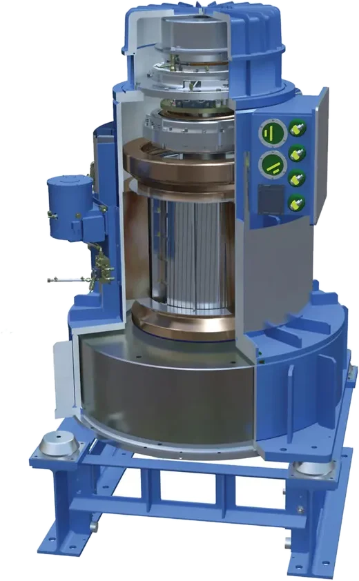
Piller POWERBRIDGE™
Energy store · Up to 60+ MJ per unit
- Energy: Up to 60+ MJ per unit
- Power / time: Above 3 MW; 1 MW for more than 60 seconds
- Space: Up to 90 % less floor space than batteries
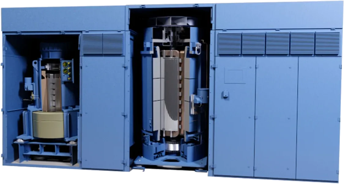
Piller DeRUPS™
Configuration · UBT+ with external gensets
- Genset: Free choice of engine and supplier
- Count: Number of gensets ≠ number of UPS
- Loads: Supplies both short-break and no-break loads
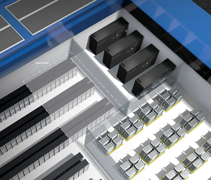
Piller Isolated Parallel (IP) System
Configuration · Low voltage up to 20 MW
- Certification: Tier IV Scheme Approved (Uptime Institute)
- Efficiency: Modules near optimum efficiency (c. 97 %)
- Size: Low voltage up to 20 MW
Active Power CLEANSOURCE® HD
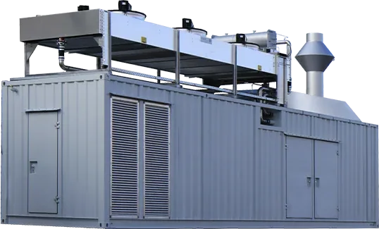
Flywheel UPS · 625 kW (50 Hz) / 675 kW (60 Hz), up to 5400 kW
- Power: 625 kW @ 380/400/415 V 50 Hz
- Parallel: Up to 5400 kW
- Efficiency: Up to 98 %
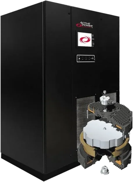
Active Power CLEANSOURCE® PLUS SMS
Flywheel UPS · 300 kW (50 Hz) / 333 kW (60 Hz)
- Power: 300 kW @ 380/400/415 V 50 Hz
- Parallel: Up to 2667 kW
- Efficiency: Up to 98 %
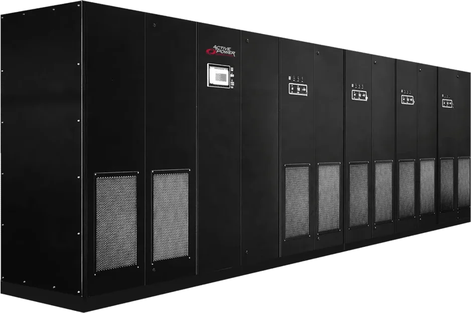
Active Power CLEANSOURCE® PLUS MMS
Flywheel UPS · 300–2400 kW (50 Hz) / 333–2667 kW (60 Hz)
- Power: 300–2400 kW @ 50 Hz
- Building blocks: 333 kW building blocks (60 Hz)
- Efficiency: Up to 98 %
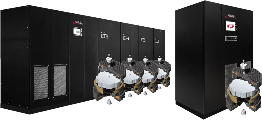
Active Power CLEANSOURCE® XT
Flywheel UPS · 225–1800 kW (50 Hz) / 250–2000 kW (60 Hz)
- Power: 225 kW (SMS) / 225–1800 kW (MMS) @ 50 Hz
- Energy: 6.2 MJ per flywheel
- Efficiency: Up to 98 %
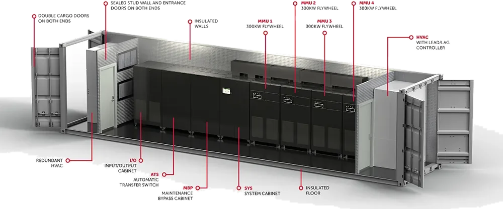
Active Power POWERHOUSE®
Containerised solution · 333–2667 kW in a 40 ft container
- Power: 333–2667 kW (standard 1333 kW)
- Redundancy: N+1 up to 2333 kW
- Ambient: −25 to 50 °C
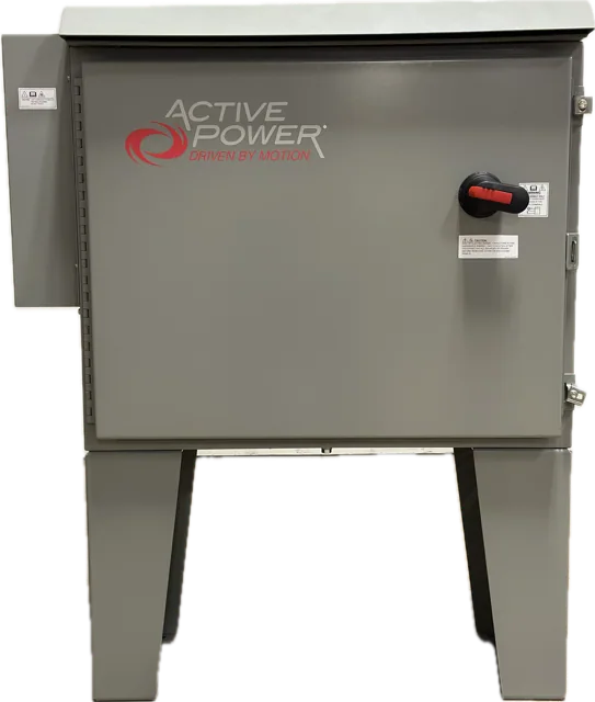
Active Power GenSTART™
Accessory · 1725 A cold cranking amps
- Cranking: 1725 A cold cranking amps
- Mounting: Floor or wall mounting
- Disconnect: Integrated AC disconnect
Images: manufacturers’ product photos.
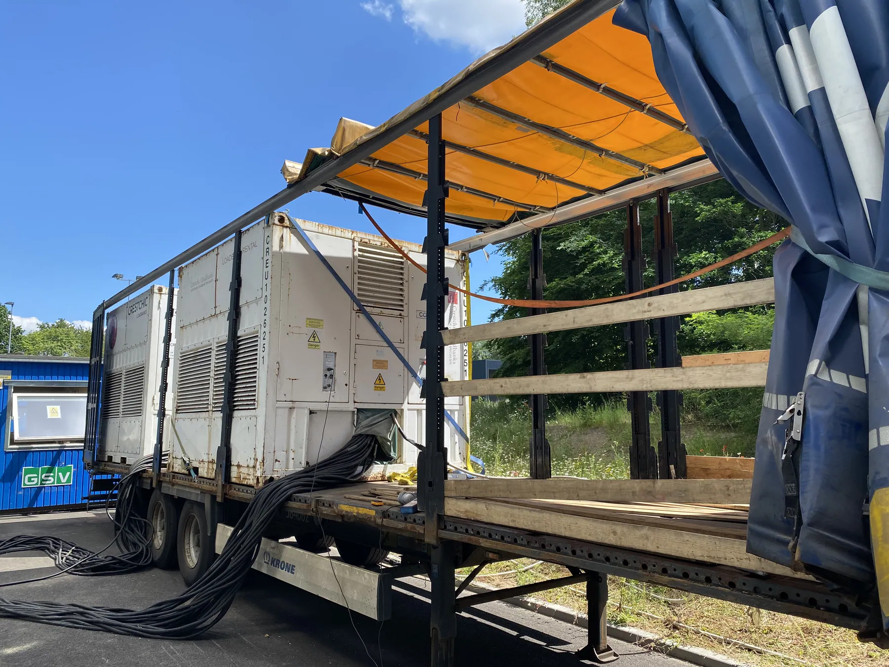
Service
Testing and maintenance
A short test that the engine starts does not prove that the standby function works. The test must show the whole sequence from mains failure to stable island mode – and back – under real load.
- 01Rotating machinesBearings, lubrication, vibration and temperature
- 02Diesel engineStart function, starting supply and preheating
- 03FuelQuality, water, filters, pumps and alarms
- 04ControlsAlarms, event log and remote monitoring
- 05Operating sequencesMains failure, island mode, synchronisation and return under load
- 06Load sharingSharing between units and response to load steps
- 07ProtectionSelectivity in both grid and island mode
- 08BuildingCooling, ventilation and exhaust in operation
Bluecircle carries out commissioning, load bank testing and UPS audits – and has a guide to DRUPS.
Standard
Specify to EN 88528-11
Static UPS systems are tested to IEC 62040-3, which does not cover rotating machines. For rotary UPS – including those with a diesel engine – IEC/EN 88528-11 applies, last confirmed in 2026. The standard describes what the manufacturer must declare and how it is tested.
- Performance class
- Limits for voltage and frequency deviations on load steps and mains failure.
- Filter properties
- Measured in both directions: from mains to load and from load to mains.
- Stored energy
- The time the energy store can carry the load.
- Efficiency
- Measured by the standard’s method – not just as a catalogue value.
- Multiple modules
- Performance when several machines work together.
- Black start
- That the plant can start without mains.
Conclusion
DRUPS must be assessed as a complete system
A DRUPS is more than a diesel engine coupled to a generator. It is an integrated power solution where energy store, machines, engine, controls, switchboards, protection and building must work together.
Ride-through, load steps, transfers, selectivity, redundancy, ventilation and fuel cannot be answered by a brochure. Start with the load profile, failure scenarios and operating requirements – and follow them through design, testing and maintenance.
What is the difference between a rotary UPS and a DRUPS?
A rotary UPS stores energy in a rotating mass and supplies power for seconds to a couple of minutes. A DRUPS is a rotary UPS with a built-in diesel engine, so the same machine also provides standby power for hours or days.
How long is the ride-through of a DRUPS?
It depends on the energy store, the load and how far the speed may drop. Manufacturers typically state seconds for systems with a flywheel on the shaft and up to minutes for flywheel UPS and systems with batteries. Ride-through must be documented for the specific configuration and load.
Does a DRUPS have batteries?
Many DRUPS systems are battery-free and use kinetic energy only. Some designs, such as Piller UNIBLOCK, can be ordered with batteries instead of or in addition to a flywheel, so check the specific configuration.
How efficient is a rotary UPS?
HITEC states up to 97% for the PowerPRO3, and Active Power states up to 98% for the CleanSource HD flywheel UPS. Actual efficiency depends on load level and operating mode and should be calculated for your load profile.
When is DRUPS better than a static UPS with a diesel generator?
DRUPS is especially relevant at large ratings – the machines start at approx. 500 kW – where space, battery replacement and component count weigh heavily. For smaller systems or long battery autonomy, a static UPS with a separate generator is often simpler. Compare the whole power chain, not just the machines.
Can a DRUPS run on HVO?
Yes. Several manufacturers have approved their DRUPS for HVO to EN 15940, including HITEC PowerPRO3 and mtu Kinetic PowerPack. Check the approval for the specific engine.
How is a DRUPS maintained?
Maintenance covers the rotating machines, bearings and lubrication, the diesel engine, fuel, cooling, ventilation, controls and protection. The whole sequence from mains failure to island mode and back should be tested under load.
Who manufactures DRUPS?
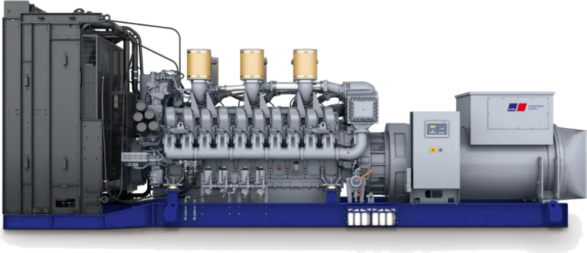
Manufacturers include HITEC Power Protection (PowerPRO), Piller (UNIBLOCK UBTD+) and Rolls-Royce (mtu Kinetic PowerPack). Piller also owns Active Power, maker of the CleanSource flywheel UPS.
How many diesel starts does a DRUPS make?
It depends on the grid, the energy store and the start delay. Most mains failures last under one second, so a plant that can delay the engine start handles many disturbances without a diesel start. Piller states that the start delay on the UNIBLOCK UBTD+ can be set from seconds to minutes.
Which standard applies to rotary UPS?
IEC/EN 88528-11 sets out performance requirements and test methods for rotary UPS, including diesel-coupled units. IEC 62040-3 applies to static UPS and does not cover rotating machines.
Can a DRUPS supply fault current for selectivity?
Yes. The synchronous machine has low sub-transient reactance and can deliver high fault current, so the breaker on the faulty feeder can trip. Selectivity must be documented with a study for the specific plant.
How long can a DRUPS run without mains?
As long as there is fuel and the engine is cooled and ventilated. The run time is set by the tank size and consumption at the actual load and must match the requirement in the contingency plan.
Read more at Bluecircle
Norwerk’s partner Bluecircle has in-depth pages on the topic.
DRUPS – diesel rotary UPS
All HITEC PowerPRO models reviewed
Read more →Load bank rental
Testing UPS and generator plants
Read more →Commissioning
Commissioning of data centres
Read more →Service plans
Response time and preventive service
Read more →Case: Google, Fredericia
Load bank test of generator plant
Read more →Do you have a project or a system that needs service?
Send us the load, required autonomy and voltage level – or describe the task. We will come back with a solution sized for your operation.